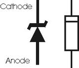
Zener Diode and its Applications

Zener diode is a type of Diode that
allows the flow of current in the forward direction similar to a
rectifier diode but at the same time it can permit the reverse flow of
current also when the voltage is above the breakdown value of the Zener.
This is typically one to two volts higher than the rated voltage of the
Zener and is known as the Zener voltage or Avalanche point. The Zener
was named so after Clarenze Zener who discovered the electrical
properties of the diode. Zener diodes find applications in voltage
regulation and to protect semiconductor devices from voltage
fluctuations. Zener diodes are widely used as voltage references and as
shunt regulators to regulate the voltage across circuits. Zener diodes
are available at the rating between 1.5 volts to 100 volts. Typical
values are 1.5V,
3.1V,3.3V,4.7V,5.1V,6.8V,9.1V,10V,11V,12V,14V,18V,24V,48V,68V etc
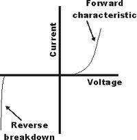
The Zener diode uses its p-n junction in
the reverse bias mode to give the Zener Effect. During Zener effect or
Zener breakdown, the Zener holds the voltage close to a constant value
known as the Zener voltage. The conventional diode also has the property
of reverse bias, but if the reverse bias voltage is exceeded, the diode
will be subjected to high current and it will be damaged. The Zener
diode on the other hand is specially designed to have a reduced
breakdown voltage called Zener voltage. The Zener diode also exhibits
the property of controlled breakdown and allows the current to keep the
voltage across the Zener diode close to the breakdown voltage. For
example a 10 volt Zener will drop 10 volts across a wide range of
reverse currents.
When the Zener diode is reverse biased, its p-n junction will experience an Avalanche breakdown and the Zener conducts in the reverse direction. Under the influence of the applied electric field, the valance electrons will be accelerated to knock and release other electrons. This ends in the Avalanche effect. When this occurs, a small change in the voltage will results in a large current flow. The Zener break down depends on the applied electric field as well as the thickness of the layer on which the voltage is applied.
The Zener requires a current limiting
resistor in series to it to restrict the current flow through the Zener.
Typically the Zener current is fixed as 5 mA. For example, if a 10 V
Zener is used with 12 volt supply, a 400 Ohms (Near value is 470 Ohms)
is ideal to keep the Zener current as 5 mA. If the supply is 12 volts,
there is 10 volts across the Zener diode and 2 volts across the
resistor. With 2 volts across the 400 ohms resistor, then the current
through the resistor and Zener will be 5 mA. So as a rule 220 Ohms to 1K
resistors are used in series with the Zener depending upon the supply
voltage. If the current though the Zener is insufficient, the output
will be unregulated and less than the nominal breakdown voltage.
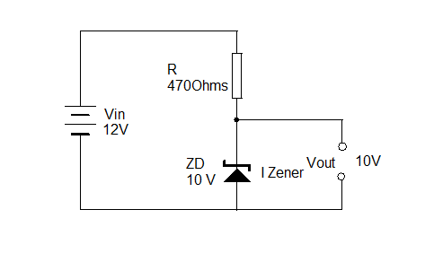 The following formula is useful to determine the current through the Zener:
IZener = ( VIn – V Out ) / R Ohms
The value of the Resistor R must satisfy two conditions.
1. It must be a low value to permit sufficient current through the Zener
2. Power rating of the resistor must be high enough to protect the Zener.
1. It must be a low value to permit sufficient current through the Zener
2. Power rating of the resistor must be high enough to protect the Zener.
No comments:
Post a Comment