IR Proximity Motor Control
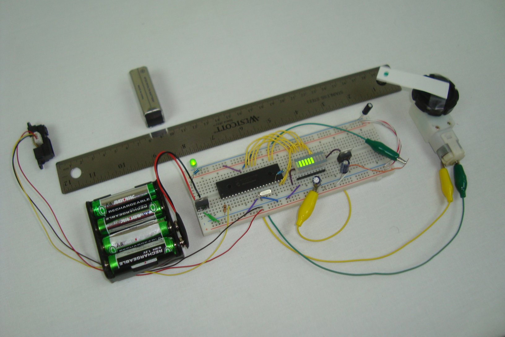
Infrared proximity sensors are very fun to play with. In the past we have used them to make
Digital Theremins and
Control Robots,
always using its proximity sensing (how far away an object is from the
sensor) as the main feature. Today, we're going on a quest to use an
infrared proximity sensor, to control the speed of a DC motor.
In this article, we will go
step-by-step through the process of understanding, designing and
building a system that uses an
infrared proximity sensor
for input, correlates that input to how far away an object is from the
sensor and then drives a motor and some LEDs at distinct speeds
depending upon the proximity of the object.
click to see the vedio
IR Proximity Motor Control - Project Setup
 Purpose & Overview Of This Project
The goal of this project and
article is to explain how to use an infrared proximity sensor to drive a
motor. The system should be able to drive the motor at 8 different
speeds (1 = slowest, 8 = fastest), likewise a representative LED bar
will be added to give a second visual speed indicator. Up to 8 LEDs will
be controlled to represent the 8 different levels of speed.
To make this system we will use a
sharp ir distance sensor (10cm-80cm) for detecting how far away the
object is, a
PIC 18F4520 microcontroller to interpret the input and drive the output, a 10
LED Bar for giving a visual indication of what speed we're at, and a
TIP42 +
DC motor for the actual motor and power transistor to drive the motor.
Parts
7805 +5v Regulator
PIC 18F4520
TIP42 Power BJT
IR Proximity Sensor
LED Bar
+3v Motor
20 MHz Crystal
3x 10uF Capacitors
Green LED
2x 100Ω Resistor
330Ω Resistor Network
10kΩ Resistor
Breadboard
Jumper Wire
+9v Battery Connector
Parts List Details
Luckily this project is half
hardware intensive and half software intensive, so there aren't too-too
many parts. Below I'll describe the most important parts in more detail.
PIC 18F4520
This microcontroller will be used
for understanding the input (an analog voltage) using its built-in
Analog to Digital converter and it will also be used to drive the motor
output and the LED bar output.
20 MHz
A 20 MHz crystal will be used to
run the microcontroller at a 20 MHz clock rate (5 MHz instruction rate).
Sharp IR Distance Sensor
This sensor is the center-piece
of this article. It outputs a specific analog voltage depending upon how
far away an object is from the sensor.
TIP42 Power BJT
To provide enough current to the
motor we need to use a power transistor. A PWM signal from the PIC will
tell the power transistor when to turn the motor on and when to turn the
motor off. The PWM's duty cycle will determine the speed the motor
turns.
Breadboard and Jumper Wire
We'll use a breadboard for
building the circuit since everything is low frequency. Standard jumper
wire will be used to connect the circuit together.
The Sharp IR Distance Sensor
There's two parts to the theory
of this project that we need to cover before looking at the schematic.
The first part is how the IR distance sensor works and the second part
of the theory section will be looking at how the motor is controlled.
The video above demonstrates in a crude manner what the output of the
IR distance sensor does when connected directly to a red LED. The
LED
gets brighter when the piece of paper nears the
sensor because the voltage output increases.
The opposite happens when the piece of paper is moved backward away
from the sensor.
The Sensor's Output
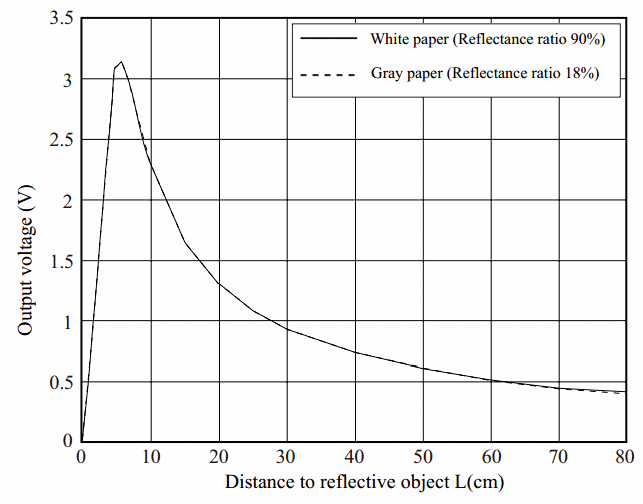
Let's take a look at the
datasheet's theoretical output vs. distance. The graph below shows what
voltage output from the sensor you should expect when a white piece of
paper is placed in front of the sensor.

As you can see right away, the output voltage is
not linear
which makes things a little annoying as we won't be able to have a
straight-forward correlation between voltage and distance. Sharp has
made a few attempts at building an algebraic equation that you can use,
check the app notes on their website for more info on those.
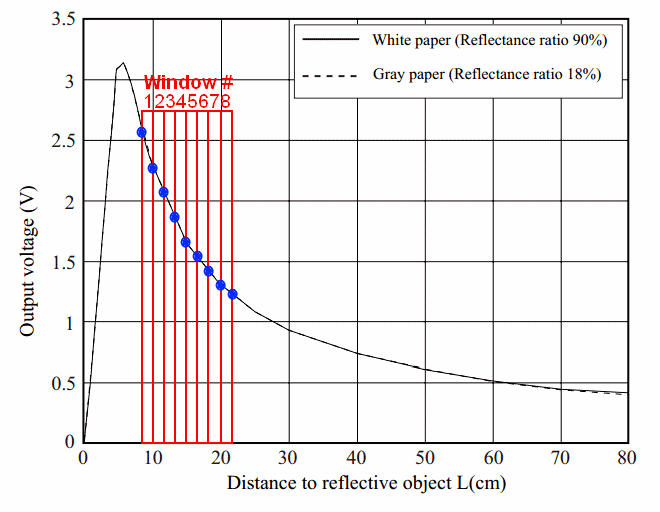
We won't be dynamically evaluating the sensor output
in this project and converting it to distance, instead we'll use set
voltages hard-coded in the software with some if statements. That means
we'll need to pick 9 voltage levels at certain distances. Below you can
see the 9 we chose and the 'windows' that those points form.

The specific distances are chosen as follows:
- Window #1 6cm-8cm
- Window #2 8cm-10cm
- Window #3 10cm-12cm
- Window #4 12cm-14cm
- Window #5 14cm-16cm
- Window #6 16cm-18cm
- Window #7 18cm-20cm
- Window #8 20cm-22cm
We call them 'windows' because each window has two sides defined
by the distance. For example if the sensor's output voltage is +2.4v,
then take a look at the graph above and you will see that we are
inbetween 6cm and 8cm, thus we're inside of Window #1's range. Our
software will create these 'windows' using IF statements.
TIP42 Motor Control
Now, we'll take a look at how the motor will be
controlled through the power transistor; the tip42. This power
transistor will receive an input pulse from the microcontroller called
PWM, pulse with modulation. Since the
TIP42 is a PNP type transistor, any time the base pin is +0v, the transistor
will be turned on and thus the motor will be turned on. To see what PWM looks like, take a look below:
PWM Explained - Pulse With Modulation

The two images above show you two
different PWM signals. The first signal is "on" 80% of the time. That
means
it is at +5v for 80% of the period of the
signal. This is a weak signal and it would make the motor for this
project run very slowly, if at all.
The second image shows you a signal similar to the
first, but it is only on 30% of the time. It
is at +0v for 70% of the period of the signal. Since this PWM signal is
in an 'off' state for the majority of the time, it
would make the motor for this project run
much fast than the first PWM.
This might seem backwards with all the 'on' and 'off'
being switched, but that is due to the fact that we're using a PNP
transistor. If you want
you could use an NPN transistor and everything would be opposite
and therefore a little more normal.
Schematic Overview
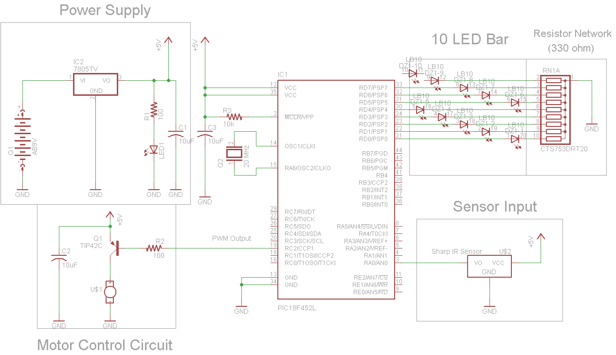
The schematic for this project has 4 main parts, the
18F4520 microcontroller, the sharp
IR distance sensor, the
power transistor and the
LED bar. You can see how these parts are connected together to build the system we want in the schematic below:

View Full Schematic
Schematic Specifics
Power Supply
To make things simple, we'll use a
7805 +5v regulator to supply the power for this entire project.
IR Distance Sensor Input
The IR Proximity Sensor has a 3
pin connector that is super simple, Vsupply, Gnd, Vout. Vsupply is
connected to +5v power and Gnd to Ground. Vout will be connecting to pin
RA0 of the microcontroller, this is an analog-to-digital converter pin.
Motor Control Circuit
The TIP42 power transistor allows
the motor to be turn off or on. The base pin of the TIP42 is connected
to the PIC microcontroller's CCP1 pin, which is a PWM output pin from
the PIC. PWM will be used to drive the motor at different speeds as we
discussed in the
theory section.
LED Bar Output
To give a visual read-out of the
current status and speed level (level 0 to 8, 0 motor is off, 8 motor is
full speed!) we'll use an LED Bar connected to the PIC
microcontroller's PORTD. This port has 8 digital I/O pins which will
each drive a single LED, on the LED Bar.
Hardware Design
Lucky for us the hardware design
and construction process is only 5 steps. Scroll down to see how it
starts out!
Putting Everything Together
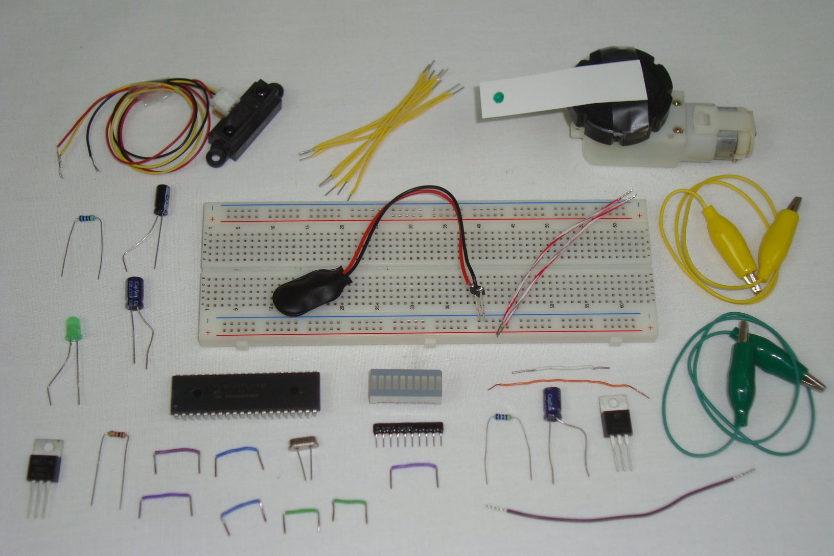
Double check you have all the parts seen in the
schematic
and get ready to start building! The first step is always gathering the
parts together so you can start building. Below you can see all the
parts. I chose to use some alligator clips to connect the motor to the
circuit instead of plain wire.

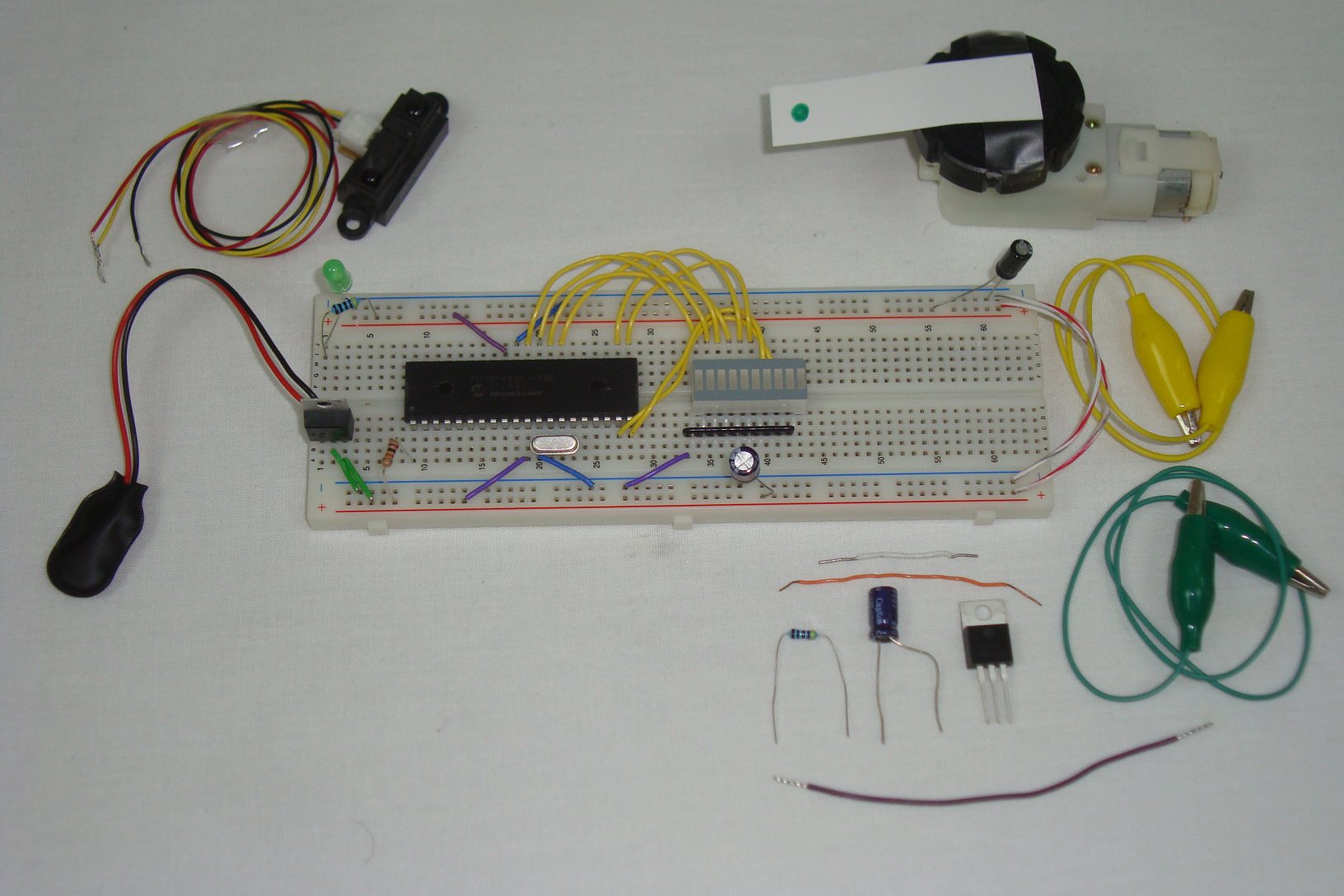
The first connections are all the power supply connections, capacitors and power LED.

Next, the basic PIC circuit is
added to the breadboard, with power, ground, crystal and 10kΩ connected
to the PIC.

Now, the LED Bar and resistor network are connected to the PIC's PORTD.

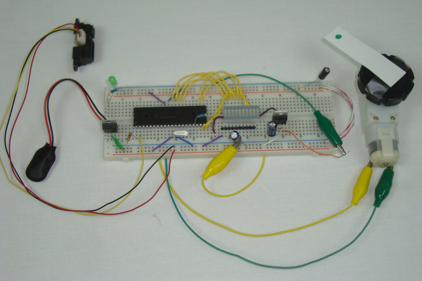
For the final step, connect the motor control circuit and IR distance sensor to the PIC.

That's it! Now let's take a look
at the PIC's firmware/software to see how we'll capture input and turn
it into nifty motor controlling output!
The Software
There are two main portions of code that we are concerned with:
-The Initializations
-Forever While Loop
The compiler used for this project is the
C18 Compiler Provided Free From Micropchip. The first part of this software initailizes the A/D converter and the PWM module in the PIC.
PIC Initializations For Motor Control
------------« Begin Code »------------
..
...
    /*
    Timer2 Prescalary Details:
    0b00 = Prescalar x 1
    0b01 = Prescalar x 4
    0b10 = Prescalar x 16
    */
    T2CONbits.T2CKPS0 = 0;
    T2CONbits.T2CKPS1 = 0;

    // PWM Frequency = [(period ) + 1] x 4 x TOSC x TMR2 prescaler
    // Tosc = 20 MHz
    // TMR2 Prescalar = 1
    // Period = 128
    // PWM Frequency = (256) x 4 x (1/20,000,000) x 1 = 19.5 KHz
    OpenPWM1( period );

    //Motor Initially Off
    SetDCPWM1( speed_0 );

    // configure A/D convertor
    OpenADC( ADC_FOSC_32 & ADC_RIGHT_JUST & ADC_20_TAD,
    ADC_CH0 & ADC_VREFPLUS_VDD & ADC_VREFMINUS_VSS
    & ADC_INT_OFF, 0 );
...
..
------------« End Code »------------
This next chunk of code is the
forever while loop which controls the motor and LED bar. This loop,
takes the sensor input data, evaluates it and then outputs to the LED
Bar and Motor depending upon the distance detected.
Forever Control/While Loop
------------« Begin Code »------------
    while(1){

        Delay10TCYx( 5 ); // Delay for 50TCY
        ConvertADC(); // Start conversion
        while( BusyADC() ); // Wait for completion
            result = ReadADC(); // Read result

        //Update Motor Speed Setting & LED Bar
        if(result < dist_6cm && result > dist_8cm){
            SetDCPWM1( speed_8 );
            PORTD = 0xFF;
        }
        else if(result < dist_8cm && result > dist_10cm){
            SetDCPWM1( speed_7 );
            PORTD = 0xFE;
        }
        else if(result < dist_10cm && result > dist_12cm){
            SetDCPWM1( speed_6 );
            PORTD = 0xFC;
        }
        else if(result < dist_12cm && result > dist_14cm){
            SetDCPWM1( speed_5 );
            PORTD = 0xF8;
        }
        else if(result < dist_14cm && result > dist_16cm){
            SetDCPWM1( speed_4 );
            PORTD = 0xF0;
        }
        else if(result < dist_16cm && result > dist_18cm){
            SetDCPWM1( speed_3 );
            PORTD = 0xE0;
        }
        else if(result < dist_18cm && result > dist_20cm){
            SetDCPWM1( speed_2 );
            PORTD = 0xC0;
        }
        else if(result < dist_20cm && result > dist_22cm){
            SetDCPWM1( speed_1 );
            PORTD = 0xFE;
        }
        else if(result < dist_22cm){
            SetDCPWM1( speed_0 );
            PORTD = 0x00;
        }

        Delay10KTCYx( 5 ); // Delay for 50TCY
    }
------------« End Code »------------
These are the two main portions
of the program. Download the full .c file at the top of the page to see
the small things I left out. Give it a compile with the C18 libraries in
MPLAB, load the hex file onto the PIC and the system is ready to go!
Data & Observations
After all of that work, hopefully
you're as eager as I am to test the system out and see how well (or
poorly =P) it works. Below is a demonstration video of the project.
As you can see, the system works
flawlessly! The distances we chose, 6cm through 22cm in 2 cm increments
were all borders of the different speeds that the motor could be
controlled at. The motor responded quickly and accurately, as did the
LED bar letting us know what speed the motor was currently at.
An Overview Of The IR Proximity Motor Control
In this project, we learned about
LED Bars, motor control with a single power transistor and about the
sharp IR distance sensor. All of those items were combined together to
make a system that could control a motor without pressing any buttons,
moving a hand back and forth in front of the sensor was all you needed.
The system seemed to operate fairly well
in the demonstration video and the PIC did a great job as the
microcontroller work-horse.
What To Do Now
Although I've used these IR
distance sensors in a variety of test, robotic and musical articles
already, there's always other areas to explore. You could consider
building an automated door opener for your pets, or perhaps a simple
logging system that keeps track of how often a door is opened. Simple
ideas, but you now have the tools to make them real!
Conclusion
The purpose of this article was
to build a motor control system that used an IR distance sensor as its
controller. In that purpose and goal we were successful. We even added a
simple LED Bar that gave a spedometer read out of the current motor
speed. All these things combined together made for a simple yet elegant
motor control system.
If you have any further questions, I implore you...don't be shy, take a look at the
forums or ask a question there. I check them out regularly and love getting comments & questions.