Showing posts with label Electronics. Show all posts

Zener Diode and its Applications

Saturday, 29 June 2013

Zener Diode and its Applications

zener
 Zener diode is a type of Diode that allows the flow of current in the forward direction similar to a rectifier diode but at the same time it can permit the reverse flow of current also when the voltage is above the breakdown value of the Zener. This is typically one to two volts higher than the rated voltage of the Zener and is known as the Zener voltage or Avalanche point. The Zener was named so after Clarenze Zener who discovered the electrical properties of the diode. Zener diodes find applications in voltage regulation and to protect semiconductor devices from voltage fluctuations. Zener diodes are widely used as voltage references and as shunt regulators to regulate the voltage across circuits. Zener diodes are available at the rating between 1.5 volts to 100 volts. Typical values are 1.5V, 3.1V,3.3V,4.7V,5.1V,6.8V,9.1V,10V,11V,12V,14V,18V,24V,48V,68V etc
The Zener diode uses its p-n junction in the reverse bias mode to give the Zener Effect. During Zener effect or Zener breakdown, the Zener holds the voltage close to a constant value known as the Zener voltage. The conventional diode also has the property of reverse bias, but if the reverse bias voltage is exceeded, the diode will be subjected to high current and it will be damaged. The Zener diode on the other hand is specially designed to have a reduced breakdown voltage called Zener voltage. The Zener diode also exhibits the property of controlled breakdown and allows the current to keep the voltage across the Zener diode close to the breakdown voltage. For example a 10 volt Zener will drop 10 volts across a wide range of reverse currents.
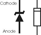
ZENER SYMBOL
When the Zener diode is reverse biased, its p-n junction will experience an Avalanche breakdown and the Zener conducts in the reverse direction. Under the influence of the applied electric field, the valance electrons will be accelerated to knock and release other electrons. This ends in the Avalanche effect. When this occurs, a small change in the voltage will results in a large current flow. The Zener break down depends on the applied electric field as well as the thickness of the layer on which the voltage is applied.
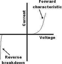
 ZENER BREAKDOWN
The Zener  requires a current limiting resistor in series to it to restrict the current flow through the Zener. Typically the Zener current is fixed as 5 mA. For example, if a 10 V Zener is used with 12 volt supply, a 400 Ohms (Near value is 470 Ohms) is ideal to keep the Zener current as 5 mA. If the supply is 12 volts, there is 10 volts across the Zener diode and 2 volts across the resistor. With 2 volts across the 400 ohms resistor, then the current through the resistor and Zener will be 5 mA. So as a rule 220 Ohms to 1K resistors are used in series with the Zener depending upon the supply voltage. If the current though the Zener is insufficient, the output will be unregulated and less than the nominal breakdown voltage.
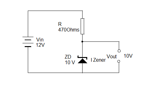
1The following formula is useful to determine the current through the Zener:
IZener = ( VIn – V Out ) / R Ohms
The value of the Resistor R must satisfy two conditions.
1. It must be a low value to permit sufficient current through the Zener
2. Power rating of the resistor must be high enough to protect the Zener.
Read more ...

Auto Switching Light

Saturday, 29 June 2013

Auto Switching Light  

                                        images

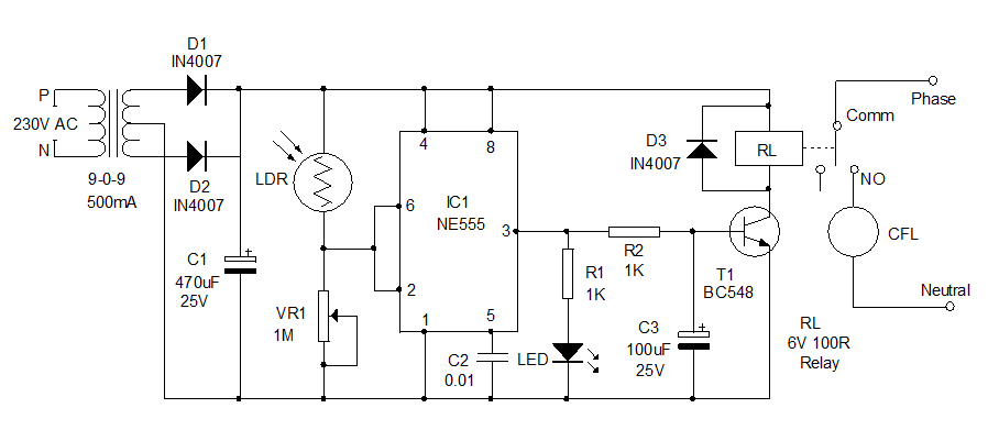
  Here is a useful home circuit for you. This automatic lighting system can be installed in your home to light the premises using CFL or Fluorescent lamp. The lamp automatically turns on around 6 pm and turns off in the morning. So this switchless circuit is highly useful to light the premises of the house even if the inmates are not in home. Generally the LDR based automatic lights flicker when the light intensity changes at dawn or dusk. So CFL cannot be used in such circuits. In Triac controlled automatic lights, only the incandescent bulb is possible since the flickering may damage the circuit inside the CFL. This circuit overcomes all such drawbacks and instantly turns on/off when the preset light level changes.

How it works?

IC1 (NE555) is the popular timer IC which is used in the circuit as a Schmitt trigger to get a bistable action. The set and reset activities of the IC is used to switch on/off the lamp. Inside the IC there are two comparators. The upper threshold comparator trips at 2/3 Vcc while the lower trigger comparator trips at 1/3 Vcc. The inputs of these two comparators are tied together and connected at the junction of the LDR and VR1. Thus the voltage provided by the LDR to the inputs depends on the intensity of light.
LDR is a kind of variable resistor and its resistance varies depending on the intensity of light falling on it. In dark, LDR offers very high resistance as high as 10 Meg Ohm but it reduces to 100 Ohms or less in bright light. So LDR is an ideal light sensor for automatic lighting systems.
During day time, the LDR has less resistance and current flows through it to the threshold (Pin6) and the trigger (pin2) inputs of IC. As a result, the voltage at the threshold input goes above 2/3 Vcc which resets the internal Flip-Flop and the output remains low. At the same time, the trigger input gets more than 1/3Vcc. Both the conditions keep the output of IC1 low during day time. The relay driver transistor is connected to the output of IC1 so that, the Relay remains de energized during day time.
Auto-Switching-Light
At sunset, the resistance of LDR increases and the amount of current flowing through it ceases. As a result of this , the voltage at the threshold comparator input (pin6) drops below 2/3Vcc and the voltage at the trigger comparator input (pin2) less than 1/3Vcc. Both these conditions cause the output of the comparators to go high which sets the Flip-Flop. This changes the output of IC1 to high state and T1 triggers. LED indicates the high output of IC1. When T1 conducts, relay energize and completes the lamp circuit through the Common (Comm) and the NO (Normally Open) contacts of the Relay. This state continues till morning and the IC resets when the LDR exposes to light again.
Capacitor C3 is added to the base of T1 for the clean switching of the relay. Diode D3 protects T1 from back e.m.f when T1 switches off.

How to set?

Assemble the circuit on a common PCB and enclose in a shock proof case. A plug in type adapter box is a good choice to enclose the transformer and the circuit. Place the unit where sunlight is available during day time preferably outside the home. Before connecting the relay, check the output using the LED indicator. Adjust VR1 to turn on the LED at a particular light level, say at 6 pm. If it is ok, then connect Relay and the AC connections. The phase and neutral can be tapped from the primary of the transformer. Take the phase and neutral wires and connect to a bulb holder. You can use any number of lamps depending on the current rating of the relay contacts. Light from the lamp should not fall on the LDR so position the lamp accordingly.
Caution: There is 230 Volts in the relay contacts when charged. So do not touch the circuit when it is connected to mains. Use good sleeving for the relay contacts to avoid shock.
Read more ...