Micro FM Transmitter ......

This circuit is commonly credited to Japanese multimedia artist Tetsuo Kogawa.
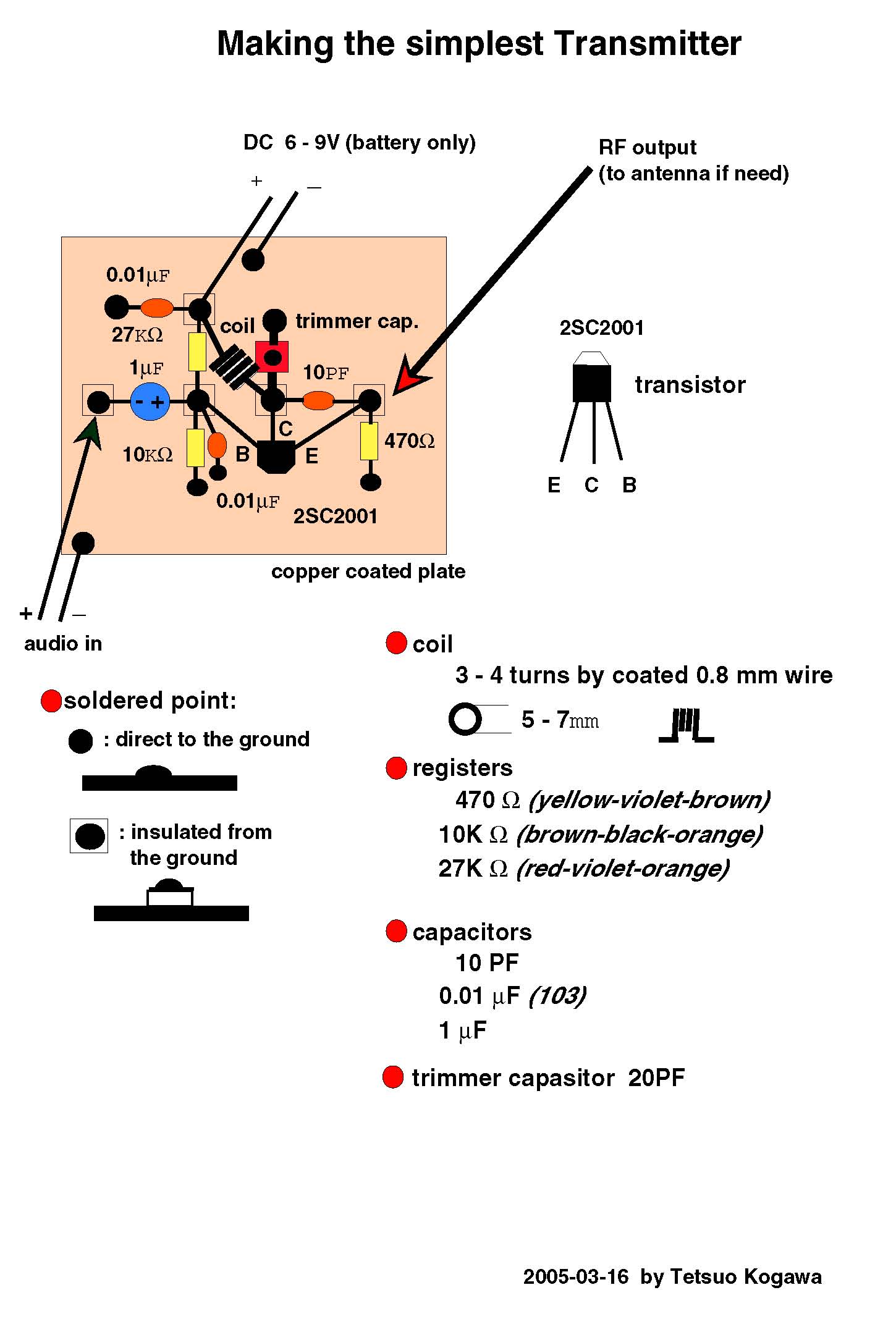
It takes audio input through a 1/4" phono jack and, constructed as
shown, without the optional antenna connections, will broadcast an FM
radio signal about 30 feet.
This is the standard model of Mr. Kogawa's simplest FM transmitter, which is slightly more complex than his most basic design in that it includes a trim capacitor to adjust the transmitting frequency. It can be powered by a 9V battery and uses a hand-turned copper coil.
I'm using the PCB and parts from Sonodrome's old kit, but the circuit is extraordinarily simple and could be built on perfboard or on a panel almost as easily. Sonodrome provides free PCB art if you want to etch your own board. Kogawa himself provides instructions for building the transmitter on an unetched copper-clad panel.
Sections
- Prep case
- Prep jack
- Form coil
- Install components
- Solder components
- Mount PCB
- Tune circuit
- Assemble
- Use it!
Tools
- 3/8" drill bit
- Audio signal source , with 1/4" phono out
- Bolt or machine screw , 1/4-20 thread For use as a mandrel in forming the coil.
- FM radio
- Helping hands
- Needle Nose Pliers
- Scissors
- Screwdriver , small To fit trim capacitor.
- Side-cutting pliers
- Soldering Iron and rosin core solder
- Wire cutter/stripper
- hand-held electric drill
Relevant Parts
- Copper wire (4 inches) , enameled, solid, 19 AWG or 20 SWG
- 1/4" TRS jack , AKA "phono jack" Only tip and shield connections are used.
- Battery holder clips , 9V, with 4" leads
- PCB , bought or home-etched or use perfboard and jumpers.
- Double-sided foam tape (1.5")
- Case , glass, wood, or plastic use your imagination! Mine was salvaged from a thrift-store digital clock. A jelly jar works great, too!
- Battery , 9V
- Mini trim capacitor , 20 pƒ
- Ceramic capacitor , 10 pƒ
- Ceramic capacitor (2) , 0.01 μƒ
- NPN silicon transistor , BC337
- Electrolytic capacitor , 1 uƒ
- Metal film resistor , 470 Ohm
- Metal film resistor , 10 K Ohm
- Metal film resistor , 27 K Ohm
- Multistrand hookup wire (8") , 24 AWG
- Bubble wrap (6 sq in)
Step 1 — Prep case
-
Disassemble your case.
-
Mark and drill a 3/8" hole, in an appropriate location, for the TRS jack.
-
At this time, you may also want to drill mounting holes
for a power switch and/or a power jack, if you choose to use an external
supply.


Step 2 — Prep jack
-
Strip about 1/2" from each end of two 4" pieces of 24 AWG hookup wire.
-
Tin the stripped ends.
-
Solder one end of one lead to the front leg of the 1/4" TRS jack, and one end of the other lead to the back leg.


