10A H-Bridge Motor Controller
Motor control is the core heart of robotics. Without locomotion or any movement a robot is dull and lifeless. The H-bridge is a tried and true concept for DC motor control. It allows you to move motors forward, backward and with varying speeds through PWM (pulse with modulation).
This tutorial will take a few steps back from the all-in-one L298 or LMD18245 motor control ICs and look more into how we can build our own H-bridge without the need of an IC.
At first this might sound like a difficult task. How can we, tiny simple people, build something that professional manufacturers put into high power ICs? Well keep reading this tutorial and you'll find out, it's actually easy!

Purpose & Overview of this project
The main goal for this tutorial is to build a 10 AMP motor controller that can control a DC motor with a digital input. This way if we want to use a microcontroller to turn the motor off or on, we can. There should be one digital input for forward and one digital input for backward. Additionally the board should have two terminal blocks, one for the motor's power and one for connecting the H-bridge to the motor.
For this design darlington pair BJT power transistors will be used to form the H-bridge. This design choice has pros and cons just like anything, but for our purposes they do the trick. An alternative power transistor that could go higher than 10A would be with HEXFETs. In reality any transistors can be used to form an H-bridge, but their different properties make some better and others terrible.
2x TIP142 NPN Transistor
2x 2n2222 NPN Transistor
2x 1kΩ Resistors
2x 10kΩ Resistors
2x Dual Terminal Block
Triple Terminal Block
Dual Layer PC Board
Ferric Chloride Etchant
Clothing Iron
Platic Container
Push Buttons
DC Motor
Soldering Iron
Solder
Power Drill
Laser Printer
Glossy Paper
Parts List Details
All the parts listed above are used in this tutorial and serve a specific purpose. The main parts are described in more detail below to give you an idea of why we need them and what it is that they do.
TIP147 and TIP142
These transistor pairs are high power (125 Watt) and high current (10A) darlington pair transistors. One is an NPN type transistor, the other is PNP. They are made to fit together specifically for H-Bridge configurations. When you see the scheamtic, it will be somewhat obvious how these pairs just fit together.
2n2222 NPN Transistor
These simple 2n2222 transistors are used as buffers beteween the digital on/off side and the analog motor control side of the circuits. A simple digital signal into the 2n2222 tells the h-bridge to go forward or backwards, the theory section will go more into the details of how the h-bridge works.
1kΩ Resistors, 10kΩ
The 10kΩ resistors are used as current limiting 'buffers' between the digital and analog portions of this circuit. They will help protect against potential damage to any digital circuits controller the h-bridge. The 1kΩ resistors are also current limiting resistors so that the 2n2222 does not get damaged when it is switched on.
Dual Terminal Block and Triple Terminal Block
Two dual terminal blocks are used to connect the motor and the power supply to the H-bridge circuit. The triple terminal block is used to connect the digital control signals: Forward/Reverse/Ground to the h-bridge.
DC Motor
DC motors are one of the simplest types of motors and we'll be controlling one of those in this tutorial. I have a few DC motors that I will use to test the circuit, anything that doesn't require more than 10A to move will do. This is probably any motor you can find that costs less than $50.
H-Bridge Schematic Overview
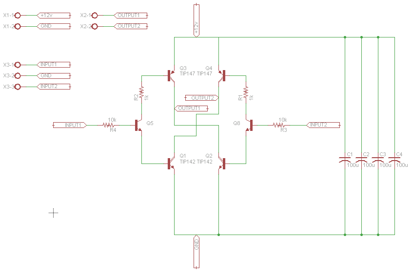
The 10A H-Bridge Motor Controller circuit looks simple but there are some key points that you don't want to miss. The main devices used in the circuit are the TIP147, TIP142 and 2n2222.
View Full Schematic
H-Bridge Schematic Specifics
Power Circuit
The power circuit is the +12v coming in from the terminal block X1-1/X1-2. It connects to a few 100uF capacitors and you might need more or less to help the motor run smoothly. The power also connects to the very top of the H-bridge (power to collector) and the very bottom (emitter to ground).
Motor Control Outputs
Outputs 1 and 2 are found in the middle of the H-bridge circuit, these connections feed into one of the dual terminal blocks, which connects to the DC motor. It is at these points of Output 1/2 where power will flow to drive the motor.
Digital Control Inputs
The triple terminal block X3-1/X3-2/X3-3 offer a way to connect up some digital circuitry and a ground to control the h-bridge. Input 1 controls one side of the H-bridge and Input 2 controls the other side.
H-Bridge PC Board Layout Overview
View Full Board Layout
H-Bridge Board Layout Specifics
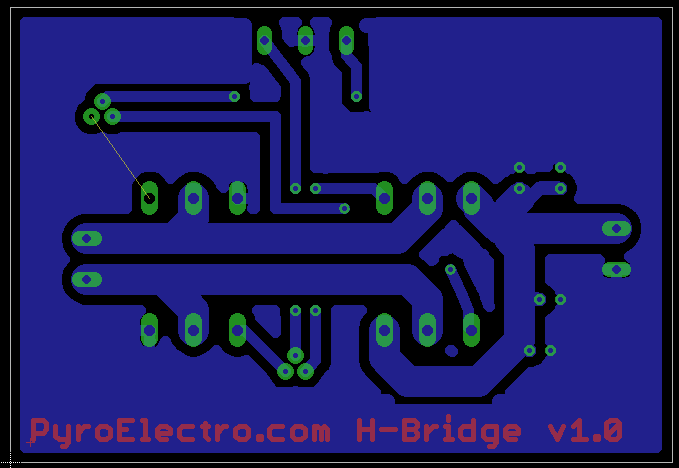
Thick vs. Thin Traces
Typically when you have high very high currents going through a PCB you want two things: thick traces and proper heatsinks. You can see the thick traces on the board above going into the dual termianl block connecting to the DC motor. The thin traces are all digital connections.
Single Unrouted Trace
One yellow line still exists, and that is because it was a trace that would cut off a good ground connection to one of the power transistors. To fix this, a simple jumper wire will be used instead of a PCB trace.
Top vs. Bottom Layer
The bottom layer (in blue) is used purely for routing the signals to the proper devices. The top layer is used purely for the name of the board and for the top of the through-hole parts.
The Theory
When it comes to contructing an H-bridge for DC motor control, there are two main things you need to know. First, you need to understand how the H-bridge itsself works. The next section shows you where the name comes from and how it works. The second thing you need to understand is the different types of power transistors available and when to use what type.
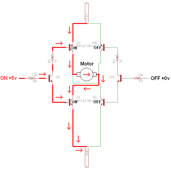
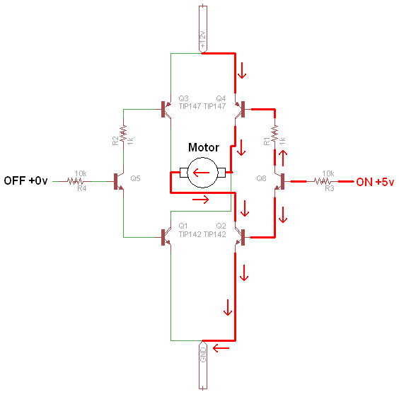
The two pictures seen above shows you the 2 possible modes of operation. Since there are only two digital inputs, you only ever need to turn one side on at a time. The two inputs should never be turned on at the same time, this will ruin your power transistors.
But as you can see. When we apply an 'on' +5v signal to one side of the H-bridge, it actives two transistors, allowing current to flow through the motor. This turns the motor one way. Similarly, when we activate the opposite side with an 'on' +5v signal, the other two transistors are turned on and the DC motor spins in the opposite direction.
When it comes to motor control and H-bridges, there's two types of power transistors that take the main stage. The Power BJT and Power MOSFET. The main difference between the two, at least as far as we are concerned is the power loss.


BJT transistors have an inherint Vce 0.7v drop, which with two transistors translates to a 1.4v drop. As you can see in the table above this amounts to about 4 Watt power loss if we're running at 3amps. That's a lot of power! The power MOSFET acts in a different way yielding a Rds 0.1Ω (some less some more) resistances across the transistor which means across two MOSFETs there is about a 2 Watt power loss.
At first glance these numbers seem not all that different, but as voltage and currents increases (+24v...+60v...) the MOSFET will win hands down with less powerloss. However, for our low voltage +12v H-bridge, these cheap TIP142/147's work nicely. There are other advantages for using BJT vs. MOSFET but I just wanted to show you this simple one. After you're an H-bridge building pro you can worry about becoming a professional designer.
PC Board Design
With the schematic build, and the board laid out we are ready to make our PCB and build the H-bridge. Making the PCB is the first step of this process so we will do that now. Get your Ferric Chloride etchant and Copper PC Board ready.
PCB Fabrication - DIY Style
Below is a quick reminder of what the top and bottom sides of the board will look like when finished. If you downloaded the printable PDF above, you'll notice that things are mirrored and not directly the same as the image below. Since we're using the toner transfer process we have to mirror these things to make sure the board isn't all backwards.

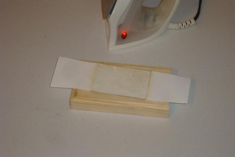
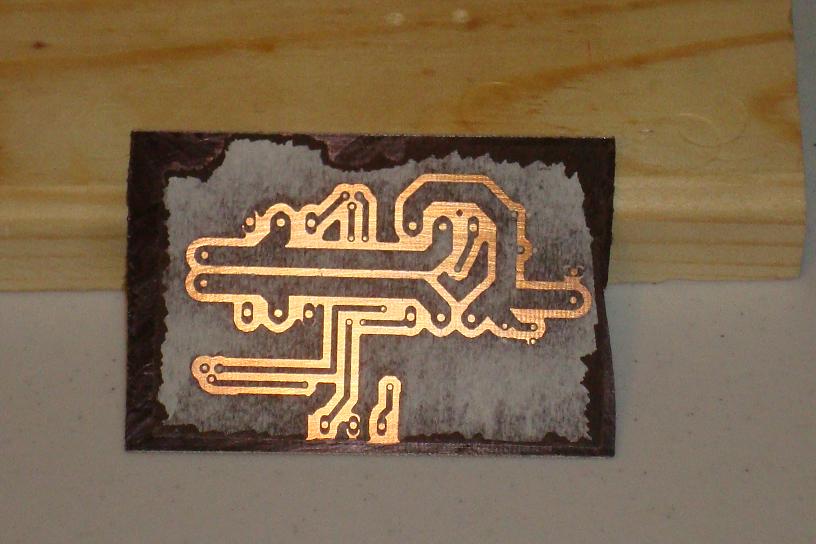
·Print out the layout on some glossy paper and cut it as I have.
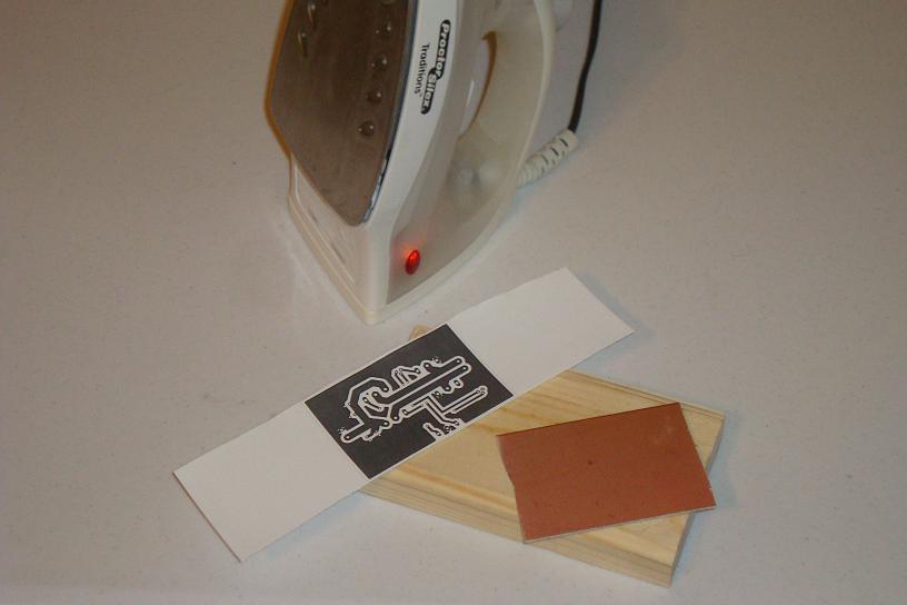
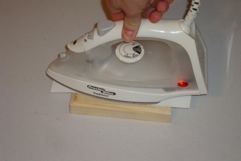
·Place the design face down onto the copper and transfer that toner!
·After a few minutes the toner is transferred. Let's do the 2nd layer.
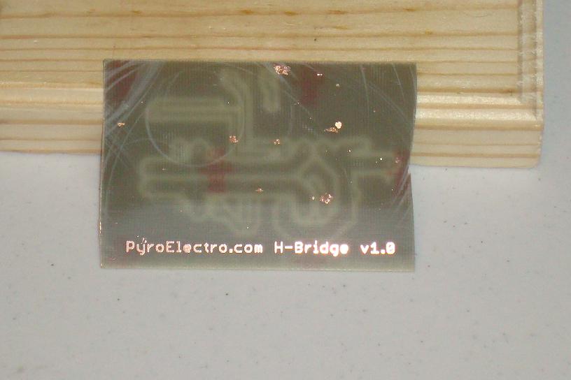
·Print the top side layout on some glossy paper and get it ready.
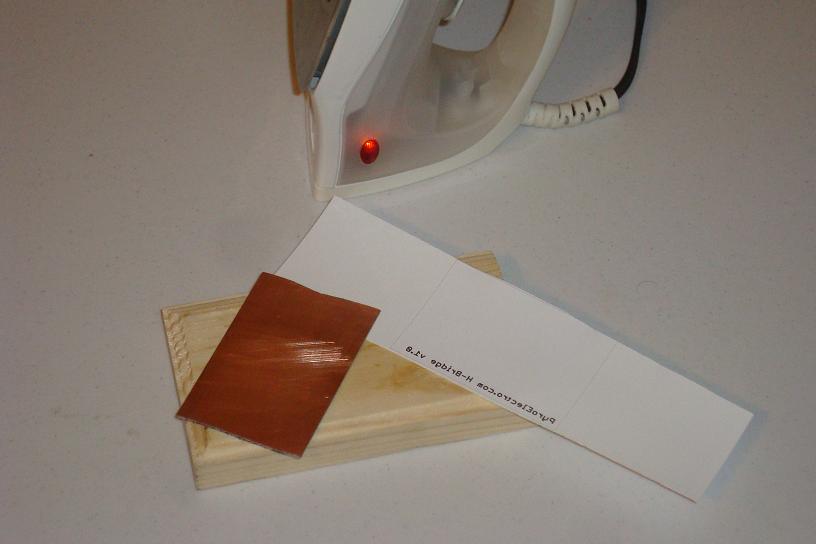
·Again, transfer the toner by rubbing the hot iron all over.
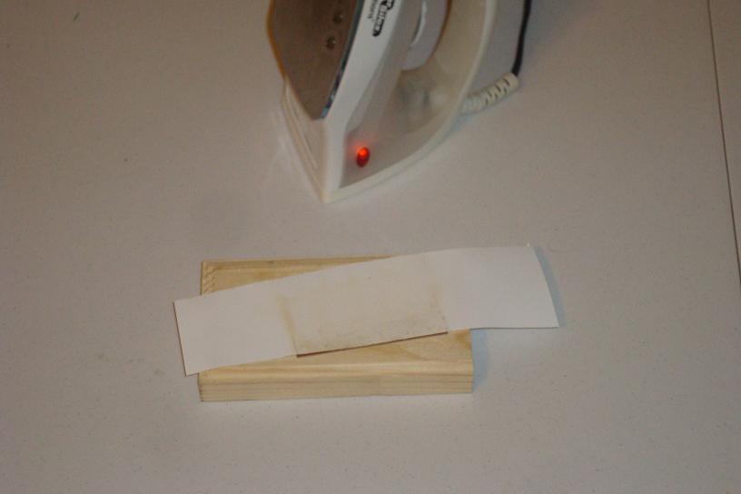
·Rinse with some warm water and you can see the transferred toner.
·Use a felt pen to touch up any spots the toner didn't transfer to.
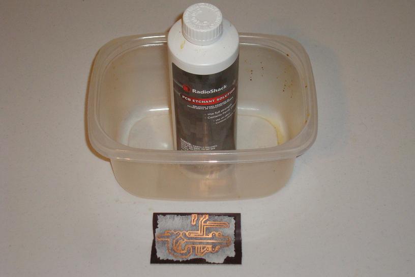
·Use some ferric chloride in a plastic container to etch the copper.
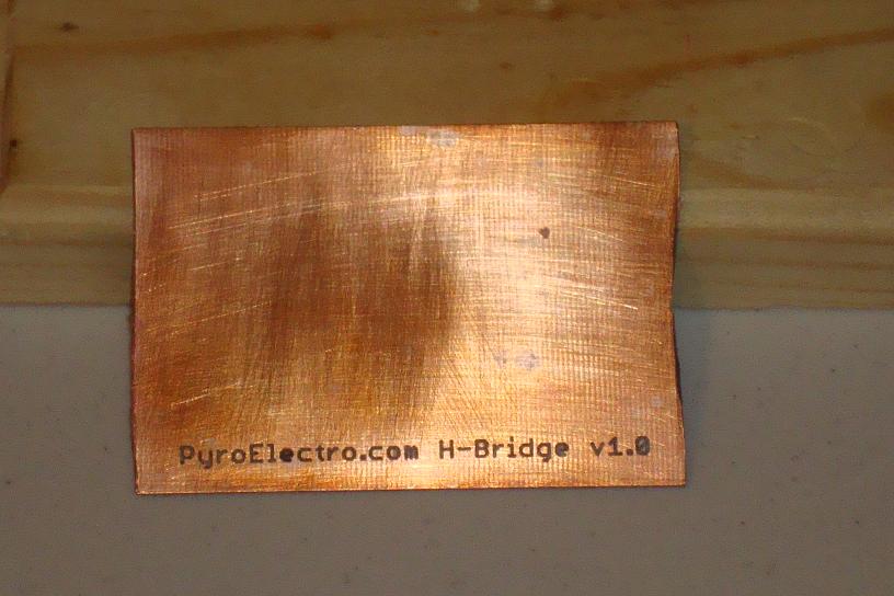
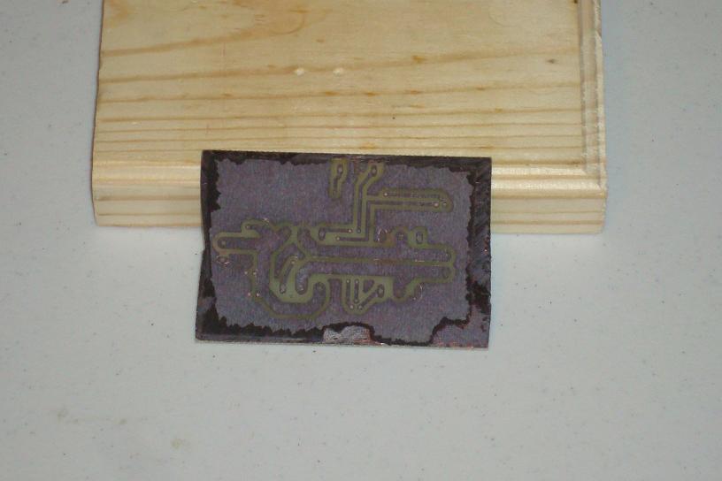
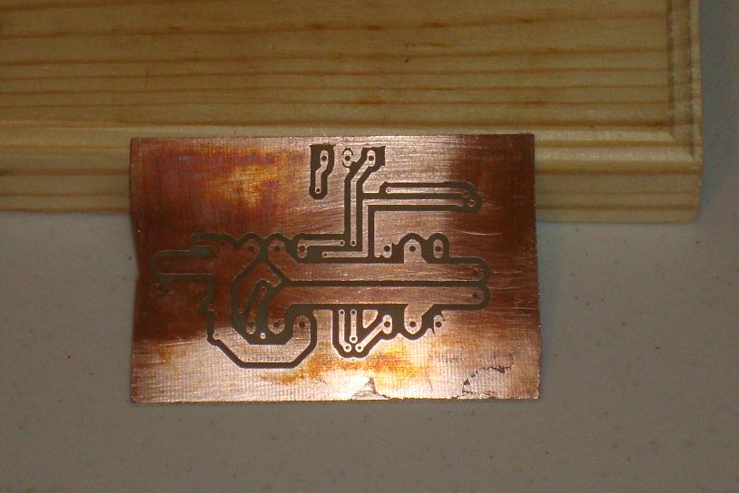
·After etching, the copper is all gone.
·Clean the toner off with a sponge. Now The Copper is very visible.
·The bottom layer copper is exactly as we designed in the layout.
·Now we are ready to assemble all the parts onto the board.
H-Bridge Hardware Assembly
Luckily the PCB was not so hard to make this time around since we didn't have to align the top and bottom layers. The top layer is just the board name. The next step is the assemble all of the parts for the 10A H-bridge. This means first you have to drill out the holes in the PCB and then solder the parts in.
Building The Circuit
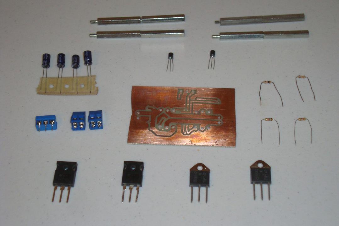
Now, get the parts together and ready to start soldering, the picture below shows everything you need to get the H-bridge put together.
·Take the 4 pwoer BJT transistors and solder them into place.
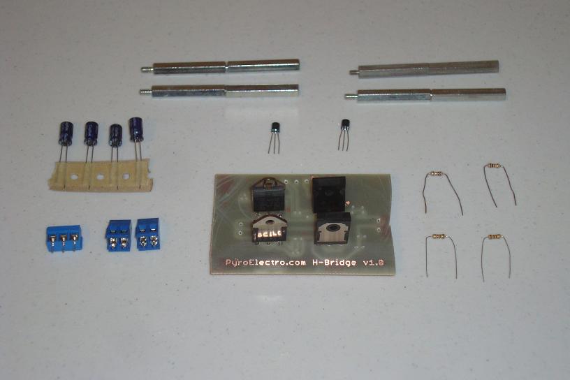
·Solder the dual and triple terminal blocks into the PCB.
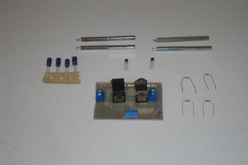
·Now, solder the 4 capacitors into place. Double check the polarity is right!
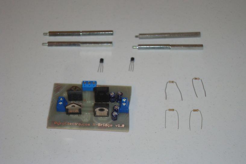
·Now the 2N2222 transistors can be soldered to the PCB.
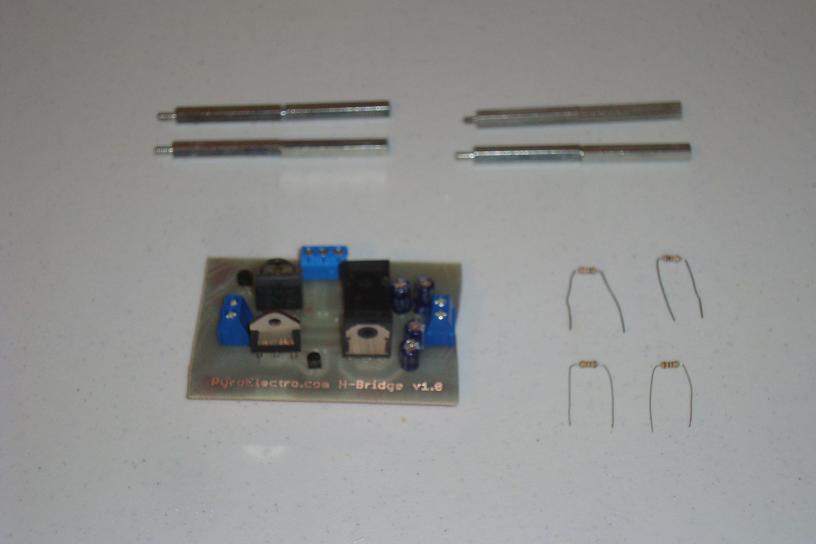
·The four resistors are the last components of the circuit to be soldered.
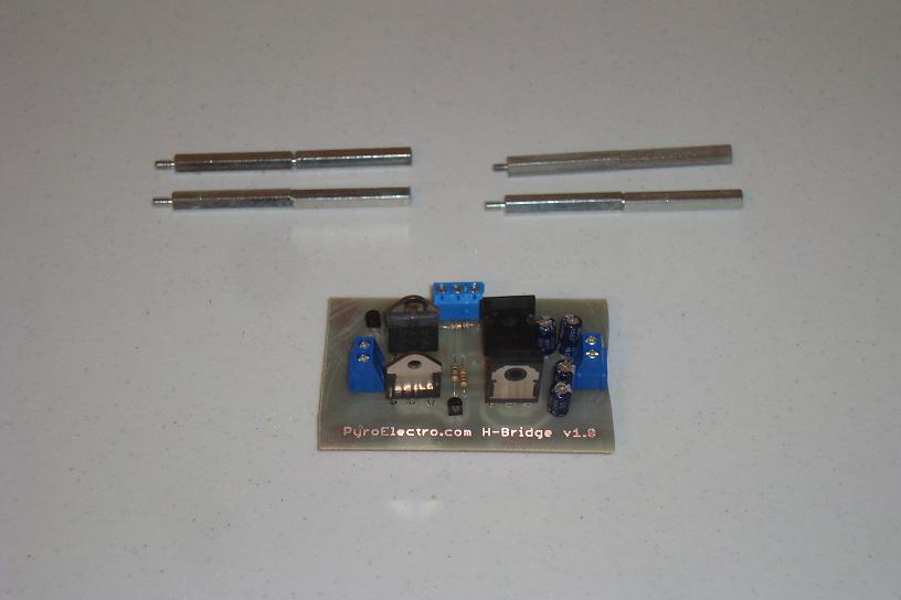
·Now drill 4 holes in the baord for the standoffs and screw them into place.
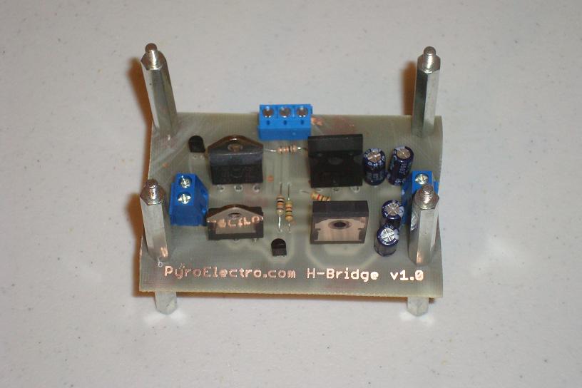
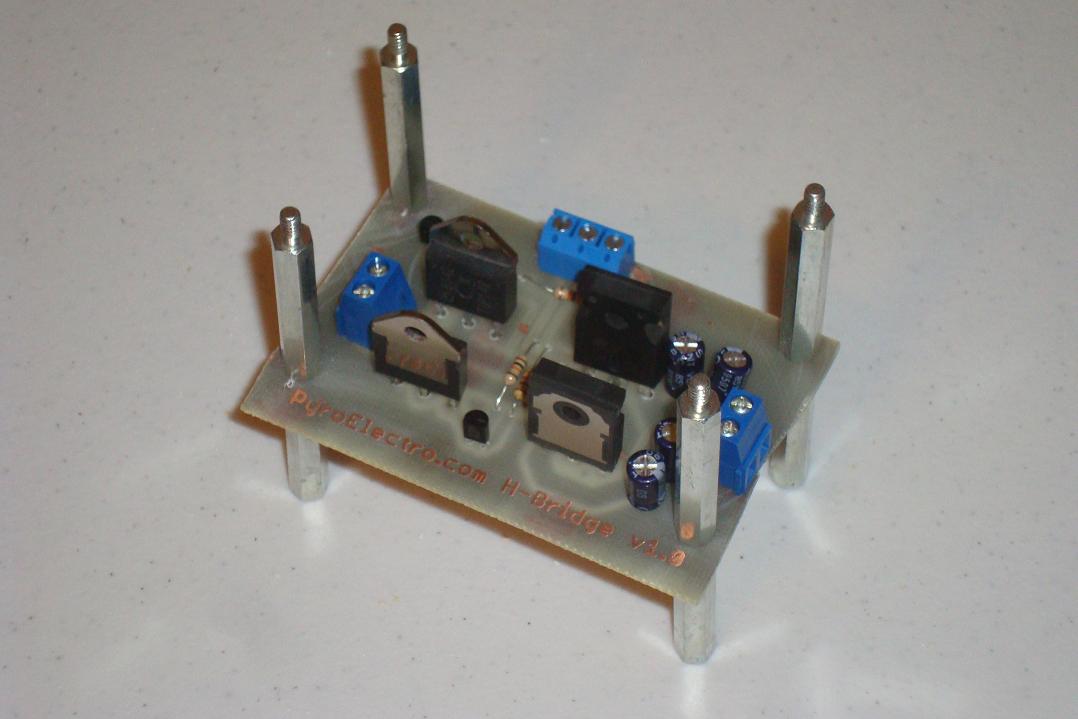
·The 10A H-Bridge is complete and ready for some action, let's test it!
Data & Observations
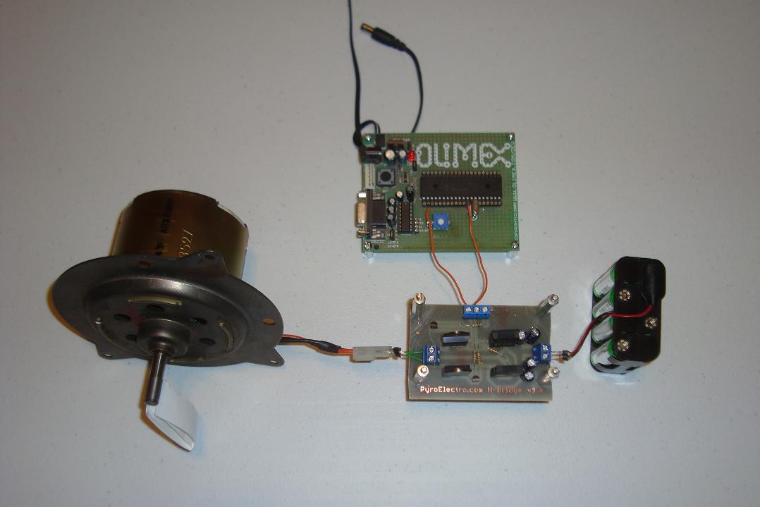
Two tests will be run on the H-bridge. The first test will use mechanical push buttons to test the forward and reverse directions to make sure that the h-bridge works correctly. The second part of the video will use a PWM (pulse with modulation) input to the H-bridge to show how adding a microcontroller allows you to vary speed.
vedio testing
There you have it! DC Motor control that works reliably and easily for under $20. I hope these videos have you convinced that DIY H-bridges can be easy and fun to make at home.
An Overview Of The 10A H-Bridge Motor Controller
This tutorial went through the theory of how the 4 transistors that form an H-bridge work and how we used them. A few transistors and resistors were added as buffers incase we want to control the motor with additional digital electronics. Overall the H-bridge is a very simple concept that luckily translates to a simple design that can be laid out and built in a single day. Testing is just as simple since not many wires need to be connected beyond power, the motor and control signals.
What To Do Now
Designing your own motor control systems demands that you know what you are doing or else things will get super hot, light on fire or simply not work. Knowing how the basic h-bridge of a motor controller works and building your own puts you on a path to understanding how almost all motor controllers work. This theory will allow you to be a better designer for your future robotics projects or anything that relies on motor control. The paths you can take from here vary tremendously from designing a more power sensitive H-bridge to designing a higher current higher voltage H-bridge for gigantic motors. Go where you want to with this knowledge!
Conclusion
This tutorial's purpose was to show you how DC motor control is done in the real world. While the design presented in this tutorial is about as simple as it gets, it is also present in almost any other motor controller that a hobbyist is going to encounter and so the theory is valid across the board. I feel this tutorial meets the goals presented in the introduction and that anyone who duplicates this board and gets it working will have a great entry into understanding DC motor control.
If you have any further questions, I implore you...don't be shy, take a look at the forums or ask a question there. I check them out regularly and love getting comments & questions.