Showing posts with label Electrical. Show all posts

Final Year Projects & Mini Projects Topics For E&TC, ECE,Electrica,EC Students

Saturday, 20 July 2013


HOME AND GARDEN:

7 DIGIT CODE LOCK
ABSORBTION TYPE METEL DETECTOR
ALTERNATING FLASHER
AUTOMATIC SLIDING DOOR
BURGULAR DETERRENT
CALL COUNTER
CENTRAL HEATING CONTROLLER
CH BOILER CONTROLLER
COLOUR WHEEL
CURRENT MONITOR AND ALARM
DECEPTIVE LOCK
DESICCATOR
ELECTRONIC BELLPULL
ELECTRONIC DOG
FLASHING WITH TWI LIGHT SWITCH
FOUR POSITION TOUCH DIMMER
HOTEL SWITCH
INDUSTRAIL CLOCK CONTROLLER
INFRA RED LIGHT BARRIER
JUMBO DIMMER
JUMBO DISPLAYS
LED DIRECTION INDICATOR
LIGHT SENSITIVE SWITCH
LIGHT SENSITIVE TRIGGER
LONG INTERVAL TIMER
MAINS BASED REMOTE CONTROLLER
MAINS FAILURE ALARM
MAINS VOLTAGE MONITOR
MAINS WIRING LOCATOR
METAL DETECTOR
METAL PIPE DETECTOR
MINIATURE RUNNING LIGHTS
MUSICAL GREETING CARDS
RANDOM LIGHTS CONTROLLERS
REMOTE CONTROL FOR LIGHT SWITCH 1
REMOTE CONTROL FOR LIGHT SWITCH 2
RODENTS DETERRENT
SET POINTER
SIREN
SND DIE
SMOKE AND GAS DETECTOR
STAIRCASE LIGHT CONTROLLER
SUPER DIMMER
TELEPHONE BELL SIMULATOR
TEMPERATURE REGULATOR WITH ZERO CROSSING SWITCH
TEMPERATURE SENSOR
THERMOMETER
THERMOSTAT CONTROLLED SOIL HEATING
TWIN BELL PUSH
TWIN DIMMER
TWO TONE CHIME
VENTILATOR CONTROLLED
WATCH DOG
WATER DIVINER


TEST AND MEASUREMENT:

8 CHANNEL VOLTAGE DISPLAY
AUDIO TESTER
AUTOMATIC SWITCH OFF
CALIBARATION GENERATORS
CRYSTAL TESTERS
DIVIDER CASCADE
FAST VOLTAGE CONTROLLED PULSE GENERATOR
FAULT FINDING PROBE FOR MICRO PROCESSORS
FUNCTION GENERATORS
GHZ PRE SCALER
INSTRUMENTATION AMPLIFIER
LINE BAR GENERATOR
LOGARTHAMIC SWEEP GENERATOR
LOW CURRENT AMMETER
MEASURING WITH THE BBC MICRO
METER AMPLIFIER
METERING SELECTOR
NOICE GENERATOR
OP AMP TESTER
POCKET FREQUENCY METER
PROGRAMMABLE BAUD RATE GENERATOR
RECTANGULAR PULSE GENERATOR
RMS TO DC CONVERTER
SERVO MOTOR TESTER
SIMPLE SWEEP GENERATOR
SIMPLFIED WORD COMPARATOR
TWO TONE RF TEST OSCILLATOR
VARIABLE WEIN BRIDGE OSCILLATOR
WEIN BRIDGE OSCILLATOR


TV AND VIDEO

RF MODULE FOR IDU
RGB TO MONOCHROMECONVERTER
SCART SWITCH
SYNCHRONIZATION SEPARATER 1
SYNCHRONIZATION SEPARATER 2
VIDEO AMPLIFIER FOR BLACK AND WHITE TV SETS
VIDEO BUFFER/REPEATER
VIDEO DISTRIBUTION AMPLIFER
VIDEO SELECTOR


More Links


List of Electronics(ECE) Mini/Final Year Projects

 Electronics (ECE/EEE) Mini Project Downloads

 Electronics (ECE/EEE) Final Year Project Downloads

 ECE Mini Project Topics

ECE Final Year Project Topics

Electrical (EEE) Mini Project Topics

Electrical (EEE) Final Year Project Topics

Latest List of IEEE Electronics Projects

List of ECE Wireless Networking Projects

Latest List of Microcontroller based Projects


Some  More Topics
Read more ...

330 volt "Shocking" Electric Deck of Cards!

Saturday, 13 July 2013

330 volt "Shocking" Electric Deck of Cards! - (Electric Shock Kissing Prank)


ps

Here's how to make a deck of cards that will pump out a shocking 330 volts of electricity.  Stuart Edge used it in his "Electric Shock Kissing Prank" to show the ladies how a man can really put the sparks in a kiss.
the king of random
See the "Stuart Edge - Electric Shock Kissing Prank"

Download the Shocker Circuit Schematic here

Step 1: Watch the Video!

vedio 


WARNING: This electric shocker outputs around 330 volts DC, and delivers a surprising jolt.  Be familiar with dangers associated with electric shocks, minor burns, damage to tissues, and possibility of cardiac arrest.  This project should not be attempted without adult supervision and adequate training.  Misuse, or careless use, of tools or projects may result in serious injury.  Use of this video content is at your own risk.

Step 2: Modified Deck of Cards - Looks normal enough

This deck of cards may look normal enough, but it has a very shocking secret!  330 volts to be exact!

I made this gadget for Stuart Edge to use in his "Electric Shock Kissing Prank"

Using a magic card trick as a decoy, Stuart and his friend Kaitlin Snow got volunteers to kiss them to see if they could "feel the magic".

When their lips touched, a 330 volt connection was made and the sparks were flying.

Check out their video to see some awesome reactions!

But .. how does it work?

This is how I made it...

Step 3: The Secret Within

The secret is in the shocker circuit integrated into the deck.

When the "stealthy"oil tape electrodes are touched by the user and the volunteer, only 1 more connection needs to be made to complete the circuit.

In this case, the circuit is completed with a kiss, and that is where the majority of the electric shock is felt.

Have you ever felt magic in a kiss?

Using the deck to charge a capacitor, and discharging on a piece of aluminum foiled demonstrates the power that can be captured from the device.

Here's how to build it...

Step 4: The Shocker Circuit

I started by heading to a local drug store and stopping at the photo center.  They usually have a whole bin full of disposable cameras ready to be shipped for recycling, and I get them free each time I ask.

For this project, I had a FujiFilm Camera, model #1A2L1701.  No particular reason for this brand, it's just the one I picked first.

If you want to follow the next steps exactly, you can look for the model number on the outside of the casing.

Opening the case, you'll find a circuit board.  This board drives the camera flash and charges an electrolytic capacitor with 330 volts.  You'll probably get shocked you if you take it out bare handed.  To avoid getting shocked, use a piece of metal to short out the 2 leads on the capacitor, as seen in the pictures.

The circuit needs to conceal inside the deck, so it has to be made smaller.  Much smaller.

To do this, desolder the 5 components seen here in my free schematic diagram and solder the components directly to themselves as depicted.

I also chose to add a AAA battery holder and a 1M Ohm tuning potentiometer to adjust the voltage output.

3 wires come off the transformer.

1 goes to the potentiometer, 1 goes to battery positive, and the other goes to battery negative, and continues on out.

This should leave 2 leads exposed, which will later be attached to the shocker pads.

The last step is to fold some paper around the circuit, and fill with copious amounts of hot glue.  This should strengthen the components by holding them firm in place.


Step 5: Rig the Deck

My shocker circuit was the equivalent of 40 cards tall, so I used a hobby knife, and a plastic template I made to cut all 40 cards in a way that would accommodate the circuit.

The circuit is a good fit, and because nothing is glued together, the cards can move freely, giving the illusion that it's just a normal deck.

To make the secret shocker pads, I cut a hold in the bottom card, and wrapped conductive foil tape (from most hardware stores) through the hole, and around both sides.  The shocker circuit sits on top, and the wires connect to each respective pad.

Note:  The hole needs to be large enough that the pads won't touch each other and short out .. and the user needs to be aware that touching them both at the same time will result in an accidental self shock.

The last 11 or 12 cards just sit on top, can shuffle freely, and give the appearance everything is normal.

The best part is, it all fits back into the original packaging.


Step 6:

Stuart Edge brought me a nicer carrying case, and it was an easy transfer.  Now this gadget was 100% ready for his kissing prank video.

You can see him holding one side of the cards (one electrode) and the guest holding the other side (opposite electrode).

When they kiss, do they feel the magic?

You be the judge.

It's important to remember that even though the amount of current flowing in this circuit is extremely low, there may be risks associated with electric shocks.  It's important to be aware of the risks, and make safety a top concern.

Step 7: Closing Up

Well, there you have it!  That's how to put the electricity in your kiss.  But it's up to you to find your partner.

If you haven't see the video yet, it's not too late.  See it here!

If you like this project perhaps you'll like some of my others. Check them out at 
Read more ...

Auto Switching Light

Saturday, 29 June 2013

Auto Switching Light  

                                        images

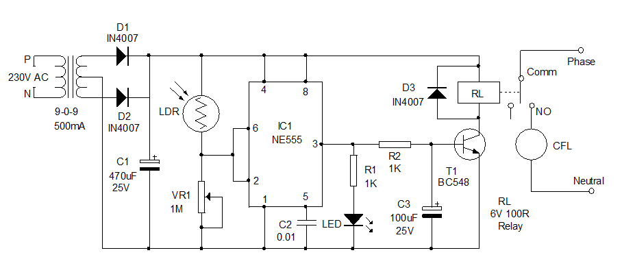
  Here is a useful home circuit for you. This automatic lighting system can be installed in your home to light the premises using CFL or Fluorescent lamp. The lamp automatically turns on around 6 pm and turns off in the morning. So this switchless circuit is highly useful to light the premises of the house even if the inmates are not in home. Generally the LDR based automatic lights flicker when the light intensity changes at dawn or dusk. So CFL cannot be used in such circuits. In Triac controlled automatic lights, only the incandescent bulb is possible since the flickering may damage the circuit inside the CFL. This circuit overcomes all such drawbacks and instantly turns on/off when the preset light level changes.

How it works?

IC1 (NE555) is the popular timer IC which is used in the circuit as a Schmitt trigger to get a bistable action. The set and reset activities of the IC is used to switch on/off the lamp. Inside the IC there are two comparators. The upper threshold comparator trips at 2/3 Vcc while the lower trigger comparator trips at 1/3 Vcc. The inputs of these two comparators are tied together and connected at the junction of the LDR and VR1. Thus the voltage provided by the LDR to the inputs depends on the intensity of light.
LDR is a kind of variable resistor and its resistance varies depending on the intensity of light falling on it. In dark, LDR offers very high resistance as high as 10 Meg Ohm but it reduces to 100 Ohms or less in bright light. So LDR is an ideal light sensor for automatic lighting systems.
During day time, the LDR has less resistance and current flows through it to the threshold (Pin6) and the trigger (pin2) inputs of IC. As a result, the voltage at the threshold input goes above 2/3 Vcc which resets the internal Flip-Flop and the output remains low. At the same time, the trigger input gets more than 1/3Vcc. Both the conditions keep the output of IC1 low during day time. The relay driver transistor is connected to the output of IC1 so that, the Relay remains de energized during day time.
Auto-Switching-Light
At sunset, the resistance of LDR increases and the amount of current flowing through it ceases. As a result of this , the voltage at the threshold comparator input (pin6) drops below 2/3Vcc and the voltage at the trigger comparator input (pin2) less than 1/3Vcc. Both these conditions cause the output of the comparators to go high which sets the Flip-Flop. This changes the output of IC1 to high state and T1 triggers. LED indicates the high output of IC1. When T1 conducts, relay energize and completes the lamp circuit through the Common (Comm) and the NO (Normally Open) contacts of the Relay. This state continues till morning and the IC resets when the LDR exposes to light again.
Capacitor C3 is added to the base of T1 for the clean switching of the relay. Diode D3 protects T1 from back e.m.f when T1 switches off.

How to set?

Assemble the circuit on a common PCB and enclose in a shock proof case. A plug in type adapter box is a good choice to enclose the transformer and the circuit. Place the unit where sunlight is available during day time preferably outside the home. Before connecting the relay, check the output using the LED indicator. Adjust VR1 to turn on the LED at a particular light level, say at 6 pm. If it is ok, then connect Relay and the AC connections. The phase and neutral can be tapped from the primary of the transformer. Take the phase and neutral wires and connect to a bulb holder. You can use any number of lamps depending on the current rating of the relay contacts. Light from the lamp should not fall on the LDR so position the lamp accordingly.
Caution: There is 230 Volts in the relay contacts when charged. So do not touch the circuit when it is connected to mains. Use good sleeving for the relay contacts to avoid shock.
Read more ...