Delay on Relay

High voltage and heavy inrush current at power on is a severe problem
that can destroy devices like TV. The transients in power lines and
voltage spikes cause high voltage in the main lines especially in areas
where there is frequent power outage. Another problem is the heavy
inrush current when power resumes after a power failure. This is due to
the generation of high magnetic field in the distribution transformer of
the power distribution system. This can cause instant breakdown of the
devices like TV if it is kept switched on state during power failure.
This simple circuit solves the problem. It gives power to the device
only after a delay of two minutes when switched on or power resumes
after a power failure. During this interval, the mains voltage will
stabilize.
The circuit works like the delay circuit in stabilizers. It uses only a few components and can be assembled easily. It works on the principle of charging and discharging of the capacitor. A high value capacitor C1 is used to get the required time delay. At power on, C1 charges slowly through R1. When it get fully charged, the SCR triggers and the relay switches on. Power to the device is provided through the NO (Normally Open) and the Common contacts of the relay. So when the relay triggers, the device will switches on. The SCR has the latching property. That is, it triggers and the current flows from its Anode to Cathode when the gate gets a positive pulse. The SCR continues to conduct, even if its gate voltage is removed. The SCR switches off only if its anode current is removed by switching off the circuit.
An LED indicator is provided to indicate the activation of the relay. Resistor R3 limits the LED current and resistor R2 discharge the capacitor.

How to Set
Setting of the circuit is easy. Assemble it on a common PCB and enclose in a case. Fix an AC socket in the case. Connect the phase line to Common contact of the relay and the NO contact to the AC socket. Neutral line should go directly to the other pin of the socket. So the phase line continues when the NO contact of the relay makes the contact with the common contact.
Photo Gallery
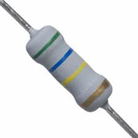
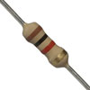
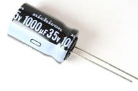
Components used in the circuit
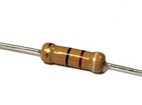
1Meg Resistor
560K Resistor 1K
Resistor 1000 uF Capacitor
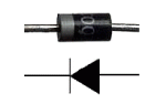
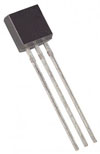
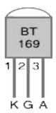

Diode IN4007 SCR BT 169 BT 169 Pins PCB Relay connection
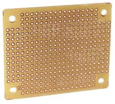
Common PCB
more circuits on http://electronicsprojectsandparts.blogspot.com/
No comments:
Post a Comment